
On this page I plan on posting diagnostic and repair procedures to help other technicians who may not be familiar with the Ford/Navistar PowerStroke.
One of my primary tasks where I work is diagnosing PowerStroke driveability concerns. Over the past four years I have seen common problems and have come up with techniques for working on this engine.
I've broken this page down into the following sections:
Open Glossary for acronyms explanations. Also see myBulletins Page for additional diagnosis and repair information and parts listing. Diagnosis Procedures
The easiest way to diagnose the PowerStroke is with an OBD II scan tool that has data stream capabilities. Unfortunatly, the 94 vehicles, while equiped with an OBD II data link connector, were actuatly EEC IV and had no data stream. By manipulating the accelerator pedal during the KOEO test, it was possible to activate an injector actuation (buzz) test, but the best way to fully diagnose these is to replace the computer with a 95 level one. This way not only are you able to retrieve trouble codes, but also run the injector buzz test, cylinder contribution test and monitor data stream and "snap shot" readings during a test drive. If you are unable to upgrade the computer in a 94 truck, it is still possible to diagnose, just not as easy. By installing a 104-pin Break-out Box and using a DVOM or lab scope you can read most of the inputs and outputs in voltage or duty-cycle.
One thing to understand and remember is the PCM reads only voltage signals from the sensors. All readings which are not displayed in volts are what the PCM calculates those sensor inputs equal. In some cases, the PCM uses one voltage input to calculate a base line for other sensor readings. For example, BARO is used to calculate MAP/MGP base line. At sea level, calculates BARO at 14.7 PSI, so a MAP reading of 14.7 equals 0 PSI MGP. At an elevation of 5000 feet, BARO and MAP would be 12.1 PSI, so the MGP base line would be recaluclated to reflect 0 and not -2.6 PSI. All ouputs are functions that the PCM is attempting to perform based on the inputs it is receiving. If there is an output device malfunction, the results may not be what the PCM is trying to achieve, but the output signal may still show normal. Some outputs may not match actual measurements. For example, the displayed duty cycle of the IPR may not match the actual duty cycle as viewed on a scope, or the displayed transmission control pressure output may not match the actual pressure on a test gauge. Strategic displays like MFDES will change as the PCM detects changes in sensor inputs which may indicate changes in environment, such as altitude, or wear in the engine. This is part of the PCM's adaptive strategy, or "learning" capability.Other tools you may want to make diagnosing this engine easier are a diesel compression gauge and long-reach adapter; an infra-red "no touch" thermometer to find missing cylinders; a 160 psi fuel pressure gauge for testing the lift pump; a standard vacuum/fuel pressure gauge for manifold (turbo-boost) pressure; and a 3600 psi hydraulic oil pressure gauge for diagnosing the high-pressure oil system. These tests are not in the original order as published by Ford, nor are they necessarily in the order in which I perform them. I modify the order depending upon the concern. While important for a lack of power concern, I wouldn't perform a fuel pressure test for a miss-fire concern. Preliminary Checks The next step is to check fuel quality. This is done by draining the fuel filter into a clean container. You'll need to attach a piece of hose to the fuel filter drain to direct the fuel away from the truck frame and into the container. The fuel should be clear or slightly amber, but not red or milky. After you drain the filter housing, remove the filter housing cover and inspect the interior for debris. Excess fuel from the injectors is returned to the filter housing, and if the injector o-rings are deteriorating, you will find find pieces of rubber inside the housing. Next you check the air filter and exhaust system for restrictions. Check the air cleaner "filter minder", look for kinks in the intake hose and exhaust pipes, and make sure that the exhaust back pressure valve on the outlet of the turbo is in the open position--rod retracted, bellcrank fully clockwise and the tang against its stop. Code Retrieval Fuel Delivery On 98.5 and newer engines: The newest version of the PowerStroke has an electric fuel supply pump. Pressure readings are taken at the fuel rail plugs at the front of the RH head, the rear of the LH head, and at the fuel pump outlet. The fuel pressure should be over 30 PSI, but anything below 50 PSI will cause an injector knock. If the pressure is low at either head, replace the check valve at that head's fuel rail inlet. If it is low at both heads and the pump outlet, check the pressure regulator at the fuel filter return line for debris or a split o-ring. If the regulator is OK, check for a fuel pump inlet restriction as described above. Computer Tests More information can be found in the Diagnosis by Symptom section.
No/Hard Start Diagnosis
As with performance problems, you first have to start with the Preliminary Checks and Code Retrieval. If the no/hard start concern happens hot or cold, you need to monitor the computer control inputs/outputs that are associated with starting. On the scan tool select VPWR, RPM, ICP, and FUEL PW PID's. If you have no scan tool you'll have to make do with monitoring VPWR and ICP with DVOM's and a break-out box, ICP with high pressure oil gauge, and CMP with a lab scope, if possible. While cranking the PID's should read 7 or more volts VPWR or VBAT (10 or more on 99 and up), 100 RPM, 500 PSI ICP, and 1-6mS FUEL PW. With the DVOM's measuring pins 97(VPWR) to 51(PWR ground) and 87(ICP sig) to 91(sig ground) the readings should be 7 and .83 volts, respectivly. Low VPWR and RPM could be and indication of a starter or battery problem. The IDM will not activate the injectors until a clear RPM signal is received, which would indicate a bad Camshaft Position Sensor
or wiring. A low ICP signal indicates a high pressure oil system problem: stuck or leaking IPR, leaking injector o-rings, no oil delivery (engine oil pump), high pressure oil pump or PCM malfunction. All readings normal except FUEL PW indicates a CMP signal sync or count problem, either the gap between the CMP and the sensor ring, a warped ring, or the CMP itself. If the glow plug system and inputs/outputs are within specifications, check fuel delivery. At the fuel pressure regulator block schrader valve, minimum pressure should be 20 PSI. If it is low, replace the filter and recheck. If it is still low check for a restriction between the fuel tank and pump by installing a vacuum gauge on the fuel supply side of the pump. If the reading is above 6 inches there is a restriction, below replace the fuel pump.
Smoke analysis More information can be found in the Diagnosis by Symptom page.
Before replacing any part on a PowerStroke engine, check the engine serial number stamped in the block next to the oil filter header. The serial number appears as follows: 7.4 HU2 U *XXXXXX*. Production changes have resulted in non-interchangeable parts. There are also parts specifically designed for California emission vehicles. Back to dieselmann's Page
Questions or comments:
For older diesel diagnosis and repair tips see my 6.9/7.3 IDI Page.
![]()
![]()
There is also a tool available from InterMotive INC. to selectivly cancel cylinders.
The first thing to do if you have any driveabilty concern on a PowerStroke is to check the engine oil level. Many problems can be traced to broken down, incorrect or low engine oil. The PowerStroke uses engine oil under high pressure (400-500 psi at idle, up to 3600 under WOT full load) to pressurize and open the fuel injectors. In effect the PowerStroke has eight 110 volt electronically-actuated and controlled injection pumps. The engine oil is therefore critical to engine operation.
PowerStroke injection explaned.
See my PowerStroke Page for the correct oil specs.
If the concern is a no-start, remove the pipe plug in the top of the high pressure oil pump reservoir and inspect the oil level, which should be within one inch of the top. If it isn't, top off the oil level.
On the PowerStroke KOEO "hard" faults must be retrieved first because any Injector Driver Module codes will be lost during the Continuous code retrieval and clearing.
After Continuous code retrieval the injector electrical buzz test needs to be performed. This done in two ways: on 94 trucks with the EEC IV connector in the engine compartment and the old PCM, after the fast codes are retrieved for KOEO and Continuous memory, depress the brake pedal to abort slow code retieval and then depress the accelerator pedal to active the injector buzz test; on trucks with 95 or newer PCM's, after clearing the Continuous memory, select Injector Electrical test from the scan tool menu. Once the buzz test is activated, the PCM will signal the IDM to actuate the injectors. First it will actuate all eight, the each one individually, in order. Listen carefully during the individual actuation sequence as each injector buzzes. Sometimes the injector will pass electrically--that is it will actuate--but the valve that the injector solenoid activates will be stuck, resulting in a muted buzz when compaired to the rest of the injectors. When this happens, I usually jump straight to the Cylinder Contribution test to confirm that there is an injector problem.
On 97 and older engines: Fuel pressure is tested at the schrader valve on the fuel pressure regualtor block attached to the LH side of the fuel filter housing. Cranking pressure should be more than 20 PSI and 30-90 PSI at WOT under load, although an idle pressure reading of less than 50 will result in lack of power or hesitation complaints. Note that California vehicles (95 and later) will have a slightly higher and fluctuating pressure readings. If the readings are low, replace the filter and check the pressure regulator for debris. If the pressure is still low, install a vacuum gauge "tee'd" into the fuel supply line. Run the engine at WOT to check for a restriction. If the reading is above 6 inches of vacuum, the supply line is blocked. If below, replace the lift pump. The last fuel system check on the 97 and older engines is a fuel-aeration check. Install a clear hose on the regulator block outlet, looping it higher than the filter housing. Start the and idle the engine and check for air bubbles after the fuel system has stabilized (approximately three minutes). Fuel should be flowing towards the fuel tank--if not, check for a restriction in the regulator block or return line--and have few bubbles. If bubbles are present, check the fuel supply system and filter housing for air leaks.
Next the KOER codes are retrieved and then the Cylinder Contribution test is run. On the EEC IV (94) engine the Cylinder Contribution test is run automatically after the KOER trouble codes are displayed. Note: Cylinder Contribution will only run if the EOT is above 170 degrees.
The PCM will shut off each injector in order and adjusts fuel delivery from the remaining injectors as it attempts to maintain engine RPM. 97 and older engines miss during this test, 98.5 and newer do not. I usually run this test twice to verify which cylinder is missing. If the same cylinder(s) do not appear twice, there may be an oil or fuel aeration problem. If you are unable to run a cylinder contribution test, you can either use an infa-red thermometer to check exhaust port temperature or inspect injector performance by removing the valve cover on the suspect injector's bank and compairing the amount of oil being exhausted by one injector to that of the others, or use the tool offered by InterMotive INC. An injector problem can be differentiated from a base engine problem by performing a compression test. Compression on the PowerStroke should be more than 400 PSI.
The remaining tests require either an OBD II scan tool or a break-out box and a DVOM. First check Injection Control Pressure stability at idle. The ICP PID reading should be 550-700 on non-California F-series, 97 and older, and 400-600 on all others--or .25 volts KOEO, .75-1 volts at idle, .83 volts require to start at pins 87(ICP sig) to 91(sig ground). Low readings could be caused by poor oil, internal oil leaks, or a high pressure oil pump, ICP or Injection Pressure Regulator malfunction. Isolating the cause can be done by disconnecting the ICP (the PCM will default to an ICP reading of 700 PSI and use other inputs for IPR control) and/or installing a high pressure oil gauge to monitor ICP pressure directly. If the concern is a rough, uneven idle that smooths out after disconnecting the ICP, The problem is most likely either the ICP malfuntioning or the IPR sticking. The manual says to replace the ICP first, but I have found that it is usually IPR. If you ever encounter an engine that runs with the IPR valve disconnected, the IPR is definitely sticking.
Next, run the engine to 3300 RPM and hold it there for three minutes. ICP pressure should be less than 1400 PSI on 97 and older Federal F-series, 1250 on Econolines and California, and 1800 on built after serial number 896812. On the DVOM at pins 87 to 91 the reading should not excede 2 volts.
Finally, test drive the vehicle and monitor Exhaust Back Pressure and Manifold Gauge Pressure (turbo boost). On the scan tool select the EBP and MGP PID's, without a scan tool measure voltage at pins 30(EBP sig) to 91(sig ground) and install a vacuum/pressure gauge "tee'd" into the MAP sensor hose. During the test drive accelerate from 2000-3000 RPM selecting gears to provide the most load on the engine. EBP should be less than 28 PSI (2 volts) on 97 and older, 34 PSI on 98.5 and newer. High reading could be caused by restricted catalytic conveter or exhaust. MGP should be at least 13 PSI within 15 seconds. Low readings can be caused by engine condition, intake leaks, inlet restrictions, fuel delivery or a worn turbocharger. One other test that Ford recommends performing is a crankcase pressure or blow-by test. To do this you need a magnehielic pressure gauge--reads in inches of water for vacuum or pressure--and a special filler cap adapter with an orifice. If you have access to this equipment, block off the Crankcase Depression Regulator valve, install the adapter in place of the oil filler cap. Attach the adapter to the gauge and run the engine at WOT. The crankcase pressure should be less than two inches of water.![]()
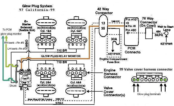
After checking the preliminaries, KOEO and Continuous codes, and the concern happens cold only, check the glow plug system function. Unplug the Engine Oil Temperature sensor and turn the key to the run position. This will cause the PCM to close the glow plug relay for the maximum of two minutes. Check for voltage to and from the glow plug relay. The control voltage is supplied by the ignition switch and the PCM controls the ground based on EOT.

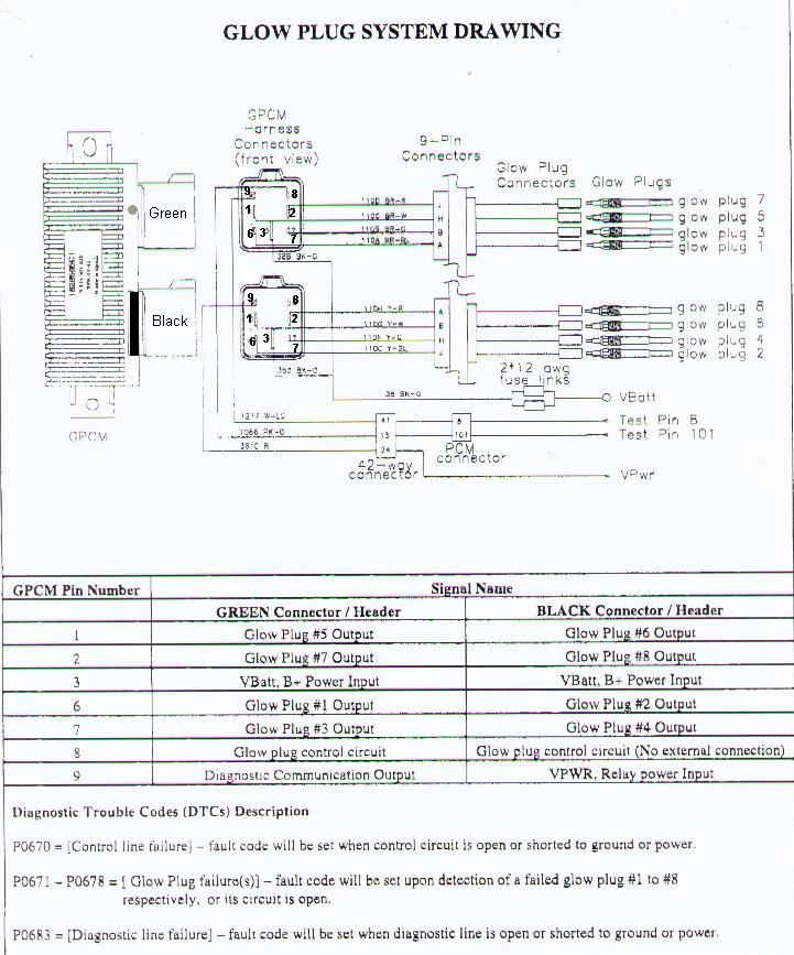
Turn the key off and disconect each valve cover harness. The two outer-most terminals of each connector are for the glow plugs. Resistance from the glow plug terminal to ground is 1-2 ohms depending on engine temperature, and from the glow plug relay output terminal to the harness connectors 0-1 ohms. 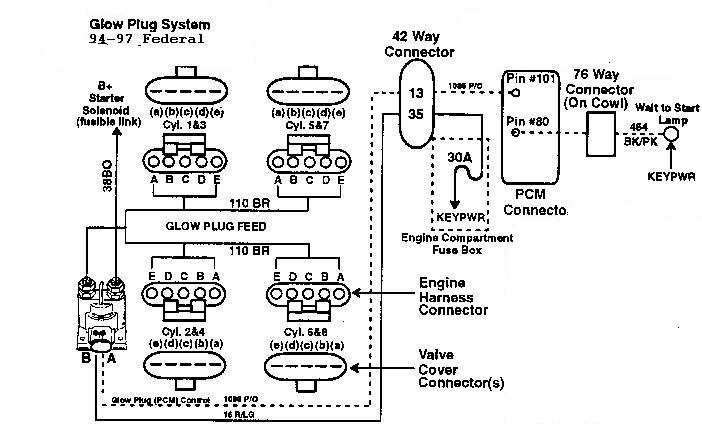
Excessive white smoke could be an indication of inoperative glow plugs, loose injectors, low compression from worn rings or bent connecting rods, or coolant leak into the cylinders--head gasket or injector well sleeves.
Excessive black smoke could result from restricted intake or exhaust, inoperative leaking or weak turbo, intake hose(s) leaks, leaking or worn injectors, fuel return or supply restriction, stuck Exhaust backPressure Regulator valve or solenoid. Also PCM inputs such as BARO MAP ICP or EBP sensors.
Excessive smoke could be caused by air in the fuel, contaminated fuel, loose or plugged injectors, worn or leaking injector o-rings, thermostat stuck open, oil consumption, or plugged crankcase depression regulator valve. Also PCM inputs such as MAP or ICP sensors.
See the PowerStroke Parts page for more details.
![]()
How the Injectors work
InterMotive INC.; Cylinder canceling tool and other devices
EASE Simulation; Windows-based PC OBD II scan tool software.
![]()

![]()
4166 Hits at last domain![]()
[Home]
[Bulletins]
[PowerStroke Page]
[PowerStroke Parts]
[PowerStroke Injection]
[6.9/7.3 IDI Page]
[Service Page]
[Tech Page]
[Symptoms]
[Repair Tips]
[Service Check List]
[Power & Torque]
[Blowin' Smoke]
[Glossary]
[Links]
dieselmann's Store ©
©  ©
©
1998,1999
![[Power & Torque]](power.gif)